Version 1
FunnyRobot Platform
Version 1
Overview
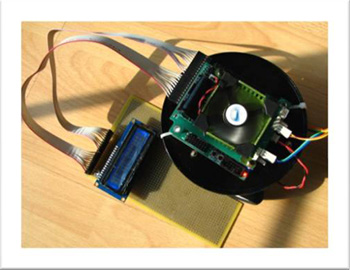
The structure of controller is a combination of a main controller and an extended board ; thus, the main controller has ability to extend peripheral devices flexibly by changing extended board. I choose ATmega128 , an advanced model of Atmel Microcontroller 8-bit AVR, to work as the brain of the robot – microcontroller (MCU) – for its abundant build-in resources and highly efficient instruction set; furthermore, two L298P chips, full-bridge surface-mounted (SMD) motor drives, control direct-current (DC) motors via pulse-width modulation (PWM). Eventually, the controller equipped eight channels of 10-bit analog-to-digital convertor (ADC), a beeper, a liquid crystal display (LCD) board, four PWM speed regulation DC motors, twenty standard digital import-output (I/O) ports, a 38KHz frequency modulator for infrared emission, and a digital compass using inter-integrated circuit (I2C) bus protocol. Moreover, the controller also reserves two channels of full-duplex universal synchronous asynchronous receiver transmitter (USART) and an I2C bus for facilitating extending other peripheral devices.
Top
Controller
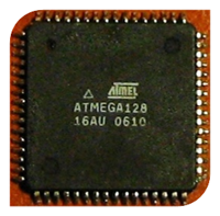
ATmega128, the processor, has a FLASH of 128K bytes, an EEPROM of 4K bytes and an SRAM of 4K bytes. Thanks to Its properties of reduced instruction set (RISC) and Harvard structure, it achieves a high calculating efficiency that almost reaches 1MIPS/1MHz; additionally, its ample build-in resources fully meet FunnyRobot’s requirement.
I design the printed circuit boards (PCB) via Altium DXP 2004 , an electronic design automation (EDA) software suite. Upon the PCB a 16MHz SMD oscillator, which improves the MCU’s anti- interference, provides the system clock pulse. Since ATmega128 has fifty-three I/O ports altogether, most of which have second functions, I reserve only twenty I/Os as standard digital ports while the others serve as their second functions such as ADC, USART, PWM, and I2C.
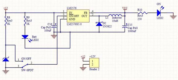
An LM2576 , an integrated circuit having high power efficiency and outputting up to 3 ampere current, offers a five voltage power to the robot.
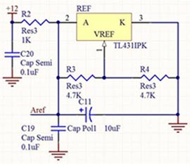
To work with the successive-approximation ADC as a precise reference voltage, a TL431 universal reference source outputting precisely at five volt works with the ADC module.
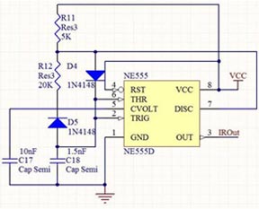
Because the infrared emission in the infrared obstacle detection system needs a 38 kHz pulse, I adopted an NE555 time base chip to be the generator; however, results of tests prove that its temperature drift is significant. As a result I replace it with a different solution in version 2.5.
The main controller provides an extended bus that draws out two two-channel 16-bit PWM motor controls, LCD ports, an I2C bus, two USART bus, the power supply, etc. The motor drive board applies some of these functions.
Top
Extended board
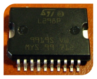
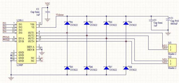
The L298P full-bridge motor drive chips on the board are manufactured into SO-20 package, which effectively declines the height of finished PCBs. Those chips having forty-six-volt-two-ampere driving ability are sufficient for controlling the motors that I choose.
The extended board carries two pieces of L298P and can drive four DC motors, each of which has four Schottky diodes to protect the circuit form overcurrent.
I placed a connector on the extended board for a LCD module that displays 16×2 characters. Unfortunately, due to the limitation of PCB size, the display module should be connected via another extended core rather than be inserted on the board.
Top
Firmware
Since the instruction set of AVR highly corresponds to the C Language, I choose AVR-GCC , the GNU C Compiler for AVR, to compile my programs for its characteristic of free software and high compiling efficiency. In addition, GCC also supports other structures such as ARM, DSP, and X86; therefore, learning AVR-GCC lays the foundation for studying the usage of other devices afterwards.

Because AVR-GCC is not released with any integrated development environment (IDE), I pick a third-party IDE called Win-AVR to develop software.

Due to the property of my driver programs, the user code should be written in a foreground-background processing structure; thus, an endless loop should serves as the stem of the program – the background – while the interrupt routines – the foreground – provide the data from hardware modules.

The driver provides standard C Language functions to control hardware modules including I2C, USART, ADC, timer/counter (T/C) , etc. as well as peripheral devices such as digital compass, DC motors, LCD, etc. It also gives users the right to monitor all ADC ports after initializing hardware resources and before running user code.
Recommend to use Firefox for browsing. Copyleft 2007 - 2010, Andygongyb's Studio
hit counter