Version 2
FunnyRobot Platform
Version 2
Overview
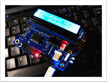
I designed the PCBs under Altium Designer Winter 09 , an EDA software suite newer than DXP 2004. The main structure and functions of controller and Extended board are identical to those of the previous version while some hardware modifications are conducted, and the major changes are described as follow.
  • The programming port changes from parallel to universal serial bus (USB);
  • I replace the original 38 kHz generator with a new one;
  • Four keys for selecting subroutines are introduced to the controller
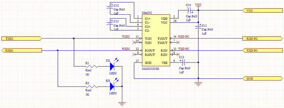
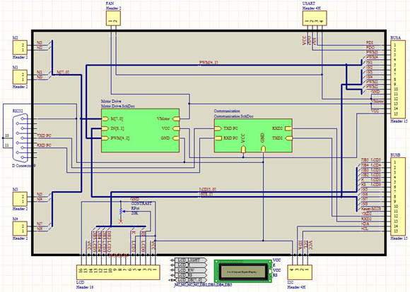
  • A MAX232 transistor-transistor logic (TTL) to RS232 level translator newly works on the extended board for communicating with devices obeying RS232 protocol;
  • The radiator fan is abandoned;
  • The new design of extended board allows mounting a LCD module;
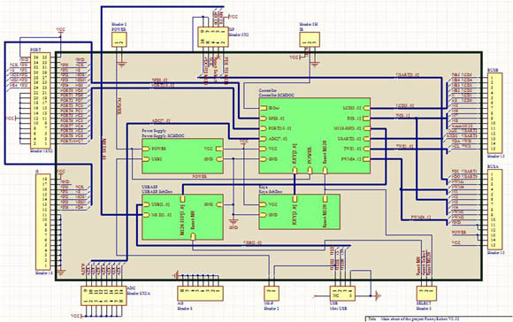
  • I redraw the schematics into layers;
  • The electrical wirings on both main controller and extended board are reconstructed.
Top
Controller
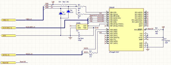
The main MCU in version 2.5 is still ATmega128; nevertheless, I introduce an ATmega8, a low-end model in AVR Mega series, to actualize the USBASP design, which allows user to program AVR devices via a USB port.
I change the former way of 38 kHz infrared emission into a combination of a crystal and an inverter, which is much more precise and reliable under different temperature circumstances; however, as a cost the maximum bearing power allowed by the new method is lower than before.
Since I port a real-time operating system (RTOS) in the new hardware driver, four keys are added in order to allow users to store a variety of tasks in the controller while programming and then to select which tasks they want to run during system initialization.
I redrew the schematics into layers: I placed the MCU part, the keys, the USBASP, and the power supply each into a separate lower layer document and connected them with each other in an upper layer document; thus, the schematics are modularized and more intelligible than before.
Top
Extended board
Rearranging the components on the extended board created a space for me to add a MAX232 chip on the board for communicating with RS232 devices including some models if vacuumed fluorescent display (VFD) and the serial ports on personal computers.
I redrew the schematics into layers: I placed the motor control part and the MAX232 module each into a separate lower layer document and connected them with each other in an upper layer document.
Top
Firmware
The hardware driver programs are totally rewritten for version 2.5. I abandon AVR-GCC and adopt AVR-G++ , the GNU C++ compiler for AVR, to develop the hardware driver. Thanks to the object-oriented programming (OOP) features, I encapsulated the drivers for all hardware modules into classes and offer users interfaces to initialize and to control the modules; thus, the code becomes much more user friendly, secure, and flexible than before; furthermore, the maintenance and update to the driver programs are easier for me. The driver for each module is also more sophisticated: it can use different functions of a module when being passed specific parameters. For example, users can determine whether to initialize a T/C to pulse-width modulation mode, timer mode, or any other mode.

However, AVR-G++ still has some restrictions such as not supporting “new” and “delete” operators; thus, I cannot create objects dynamically. Although the standard C Language function malloc() can allocate memory dynamically while function free() can release the memory, they do not support OOP: they never call the constructor and destructor of an object; therefore, AVR-G++ still does not meet my require perfectly.

During the development of driver version 2, I use a different IDE from that used in the previous version because the new IDE – Eclipse – is more powerful in source code management and in providing code context, which enhances my coding efficiency considerably.

The driver program for version 1.0 instructs users to write foreground- background processing client code; nonetheless, the driver for version 2.5 equips a preemptive RTOS called FreeRTOS , which also supports time slicing tasks; thus, the user code is not an endless loop, instead, should be written in several subroutines. I embed AVRX into my own programs to make it more powerful: users can select different tasks to run each time when the system starts.
Recommend to use Firefox for browsing. Copyleft 2007 - 2010, Andygongyb's Studio
hit counter